
ESPCLOCK4 - Reduce operating current by removing UART module

The ESP32 Mini uses a CP2104 UART module to drive the USB port.  The CP2104 is configured in self-powered mode, which means that even if nothing is plugged into the USB port and the board is powered by a 3.3V source, it is still drawing ~100uA of current. I wanted to see the effect of removing this module on the power consumption of my test circuit.

Removing the UART module means losing access to the USB port. However, I should still be able to program it using a standard FTDI programmer, which I wanted to verify. So I took out the same FTDI programmer that was used for programming the ESP8266, and built a custom holder for the ESP32 Mini.


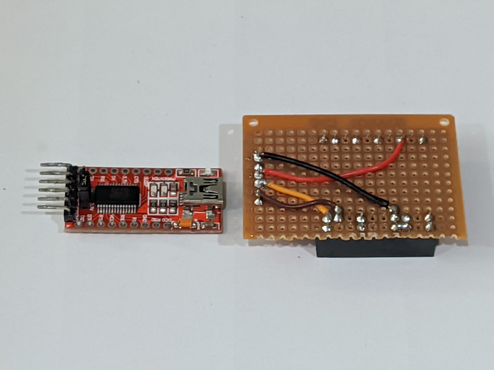
I started with the same connections as used with the ESP8266:
  • ESP32 VIN <-> FTDI 3.3V
  • ESP32 GND <-> FTDI GND
  • ESP32 TX <-> FTDI RX
  • ESP32 RX <-> FTDI TX
However, I could not get it to work. After some fiddling around, I discovered I could only get it to work by connecting RX - RX and TX - TX. Not sure why.

But now I am confident I can still program the board without its USB, so I proceed to remove the CP2104 module (marked in red) with a hot air gun.


After removing the UART module,  I verified that the board was still working by uploading the code here, and plugging it into the test circuit. Sure enough, the clock started ticking. It worked!

I then tried measuring the current consumption using the LTC4150. Unfortunately, the current seems too low to be measured. After doing some research, I decided to swap out the 0.05ohm sense resistor with a 1ohm resistor. Because I didn't have a 1% part, I simply used a normal 5% metal film resistor. However, I did calibrate it against a multimeter with a 10kohm resistor over a 3.3V power source. I found the measurement to be within ~20uA tolerance.

Note: with such small current, the power used by the LTC4150 itself becomes very important. From the datasheet, at 2.7V, its typical power usage is 80uA, with a max of 100uA. With a 10Kohm passive load, I got a reading of 430uA. Substracting 90uA from the reading gives me 340uA, which compares well with the multimeter reading of 326uA.

Using a 1ohm sense resistor means I can no longer use WiFi in my test code. The 500mA current drawn will cause the board to brown out and reset.

So finally, with the UART module removed, the current draw is 650uA - 90uA = 560uA, or ~0.6mA. This is a hugely improvement over the 1.13mA that I measured previously with the UART module intact.

So it looks like I am going to go ahead and create the full ESPCLOCK code with this setup.

Comments

Popular posts from this blog

Update: Line adapter for Ozito Blade Trimmer

Update (Dec 2021): If you access to a 3D printer, I would now recommend this solution , which makes it super easy to replace the trimmer line. I have been using it for a few months now with zero issue.

Cooling mod for the X96 Air

I realized after my Ugoos box died that overheating is a big problem with cheap Android TV boxes. A teardown of the Ugoos box shows that it does not have any heatsink or fan at all!  The X96 Air does have a heatsink, but the heatsink is located at the bottom of the casing with no ventilation. In this default configuration, with the ambient room temperature at 25c and playing a 1080p video, I was seeing the CPU temperature at 67c. I drilled a couple of holes at the bottom of the casing. The CPU temperature fell to 59c with the box raised about 2cm with plastic blocks. I retrieved an old 5V laptop fan: Then cut and strip away a spare USB cable: Solder the red and black wires on the fan and the cable: Secure the fan to the bottom of the casing with double-sided tape, then plug the fan into the box's USB connector. Here's a view of the box with some 3D-printed risers installed at the bottom to give the mounted fan sufficient clearance: The CPU now runs at 43c, a huge drop from the ...

Installing and customizing CoreELEC in X96 Air

I previously installed CoreELEC on another TV Box ( Ugoos X3 Pro ), which unfortunately died after only 9 months during the summer (due to the unit overheating, which I learned is a common problem for cheap Android TV boxes). So this time I purchased a X96 Air  (4GB/32Gb) and had to do the whole thing again. So this is a note-to-self in case I ever have to install CoreELEC again on some other device. Installation of CoreELEC is simple enough by following this guide . Basically, it involves downloading and writing the firmware to a microSD card using usbimager . Then insert the microSD card, reset the unit and hold the reset until the logo appears. The unit will then proceed to boot into CoreELEC. First thing is to connect to WiFi, then enable SSH. This allows me to login via ssh and execute: ceemmc -x from the terminal. This writes CoreELEC to the built-in eMMC storage, after which I am able to remove the microSD card and reboot the unit into CoreELEC via the built-in sto...